Rule-Based economic control of HVAC system
Part of the series University projects (5 posts total).- May 18, 2023 - My university projects
- May 18, 2023 - RoboCup: Autonomous line following robot competition
- Jun 06, 2023 - Hi-Fi amplifier for record players
- Jun 07, 2023 - Homemade embedded CPU on an FPGA
- Jul 02, 2023 - Rule-Based economic control of HVAC system
On my 7th semester of university, I was part of a project in which we designed a controller for an on-site heating- cooling and air conditioning (HVAC) system. The idea was to utilise a massive water storage tank to act as a thermal buffer, capable of storing energy while the electricity prices are low, releasing it once the prices rise.
The system
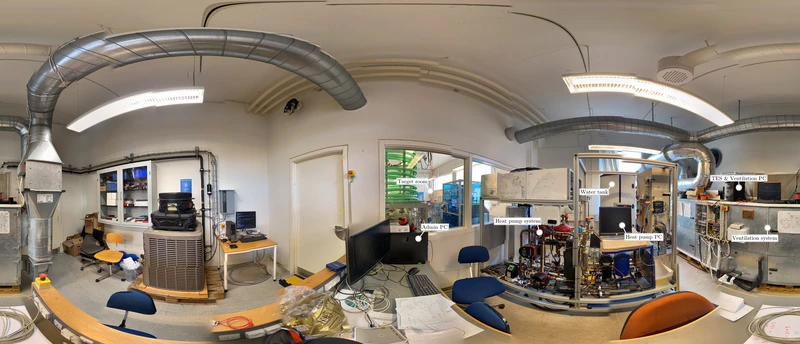
Panorama view of the HVAC laboratory at Aalborg University. Click here for the full picture with labels.
The system consists of a ventilation system, which has two ducts with fans moving the air between outside the building and the airconditioned room, called the target room. Inside the ducts sits a tube capable of heating the air if it is supplied with hot water. This hot water is produced by the heat pump which moves thermal energy from the control room to the cooling liquid and subsequently to the water. This process is known as the refrigeration cycle. Instead of sending this water into the ventilation ducts, it can also be redirected to an insulated water tank, storing the energy for later. This is denoted thermal energy storage (TES) on the picture above.
The system required enormous amounts of wrangling to get working, as there was a severe lack of documentation and other issues.
- The compressor in the heat pump broke due to excessive liquid accumulation and a technician was hired and replaced it.
- Safety measurements to prevent the aforementioned failed and we implemented a new start up sequence to ensure sensible heat on the refrigerant prior to compression.
- Several sensors had lost signal and two sensors where switched around.
- A hole was drilled in the wall for mounting an ambient temperature sensor.
- The TES held an unspecified amount of water inside. To inspect this we opened it up, but the large water pressure caused water to spray out in the entire laboratory.
The communication system
During operation, the laboratory was hot and very noisy.
Furthermore, HVAC systems generally have slow dynamics, and proper experiments can take many hours and even days.
For these reasons, we decided to program a communication system which allows us to control the system from outside or at home.
Diagram of the communication setup established in the laboratory.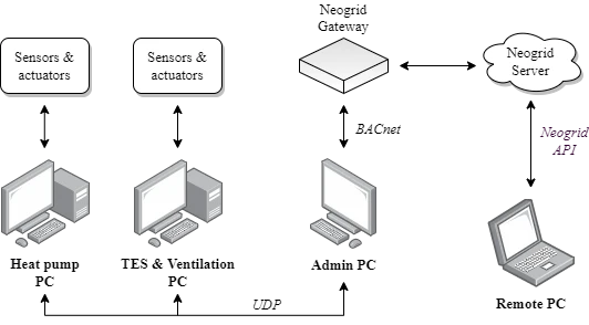
The heat pump is controlled using a PC with a proprietary MATLAB embedded operating system (OS) Simulink Real-Time running off a single CD (this is real btw.). This is also the case for the other computer which manages the ventilation system (fans and such). The last PC, the Admin PC, acts as the control hub for both allowing for implementation of controllers using MATLAB Simulink. Truth be told, I really dislike this setup, but we didn’t have time (or authority) to remake the system.
First we programmed the OS using Simulink to send the data as an UDP packet over LAN. A Python script on the Admin PC listens for these packets and stores them in memory. Meanwhile, the Python program acts a device in the BACnet communication standard. A unit provided by the company Neogrid prods this device for data at a scheduled rate, and sends it to be stored on a server. This data can then be accessed by a device outside using the Neogrid API or website. Communication in the other direction is much of the same.
The model & controller
On the 7th semester, we hadn’t learned of non-linear control methods, so we sufficed with creating two different modes of linear control. In the discharging mode, the heat pump stops delivering heat to the water, and solely the water inside the TES is used to heat the ventilation air. In the charging mode, the heat pump delivers heat to the water which is redirected to both the TES and the ventilation duct, depending on the opening of a valve. We design a thermal model and fit the parameters by hand.
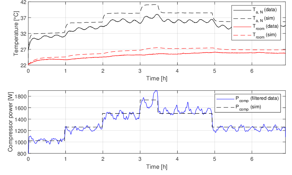
Ventilation air temperature, room temperature and compressor power consumption for simulation and data.
The discharging mode is controlled using a small-signal PI-controller with saturation and anti-windup. The charging mode controller is a bit more difficult to explain. In essence, a small-signal PI-controller with saturation and anti-windup controls the opening degree (OD) of the valve to the TES wrt. a ventilation temperature reference. Meanwhile, a proportional controller satisfies the OD from another proportional controller which controls the TES temperature wrt. to a setpoint.
This setpoint, along with the current operating mode of the system is determined by a different controller, called the Rule based price controller (RBC) for price reduction.
This RBC follows the following rules:
Decision flowgraph when the electricity price is rising. Decision flowgraph when the electricity price is falling.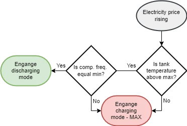
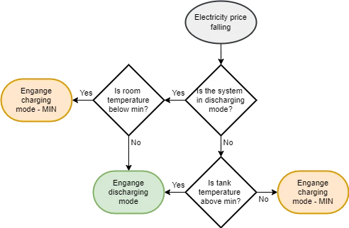
I will not go into detail here, as this requires explaining a lot of the choices I refrained from explaining earlier. The price rising or falling is dependent on an algorithm we sourced from a paper. Simulations show, that this RBC proves a cost reduction of between 1 and 7% depending on the outside temperature.
The academics
This project required we wrote a scientific article to presented at the mock-up convention SemCon at Aalborg University. Writing the paper was a new experience and it was quite difficult to compress the 80 or so pages of worksheets into 6 comprehensible pages. You can read it here. It isn’t ground-breaking by any means, as most of the time was spent learning the ins and outs of the HVAC laboratory. Still, I think we nailed the format. There was also a poster, which currently hangs on a wall somewhere on university.
Published 2. July 2023
Last modified 2. July 2023