Hi-Fi amplifier for record players
Part of the series University projects (5 posts total).- May 18, 2023 - My university projects
- May 18, 2023 - RoboCup: Autonomous line following robot competition
- Jun 06, 2023 - Hi-Fi amplifier for record players
- Jun 07, 2023 - Homemade embedded CPU on an FPGA
- Jul 02, 2023 - Rule-Based economic control of HVAC system
My fourth project at Aalborg University, which, akin to the line-following competition is an Aalborg University tradition. The year prior hosts the courses in basic analog circuitry, while the semester corresponding to this project features a course in transistor and opamp theory. Therefore, it is customary to chose a transistor/opamp project. We decided upon designing a low-noise (Hi-Fi) amplifier for a record player.

All the components used in playing a vinyl.
In the picture above, disregarding the two voltage sources, the components are from left to right:
- The record player, with no active amplifciation.
- The pre-amplifier which amplifies the signal to line level and applies a RIAA correcting filter.
- A switch for switching between record player and phone line in.
- The main amplifier raising the signal from line level to appropriate speaker level.
- The passive speaker, which plays the audio.
The record and the player
Looking at how a record player works, it is clear why amplification of the signal is needed.
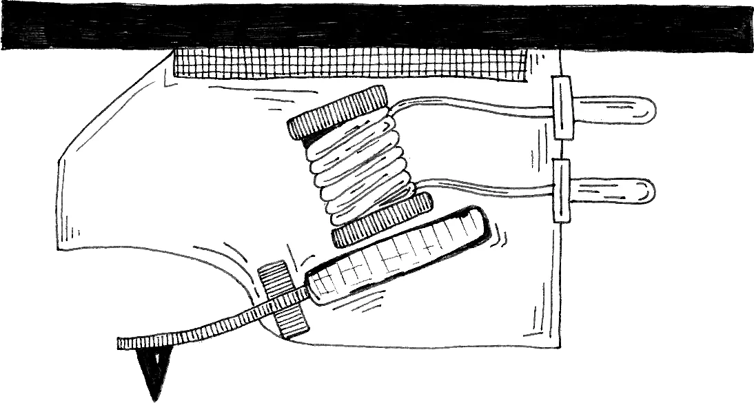
Diagram of a record player pickup, with needle, attached magnet and inductor.
The end of the record player is called a pickup. As the needle moves according to the grooves in the vinyl, the magnet inside moves inducing a current in the inductor as stated by Ampère’s Law. Some pickups have the inductor attached to the needle instead. The movements are so miniscule that almost no current is induced in the inductor and definitely not enough to hear through a speaker. This is where amplification comes in. While many think that amplifiers for listening use are a thing of the past, they have simply been moved into the speakers in what is known as an active speaker.
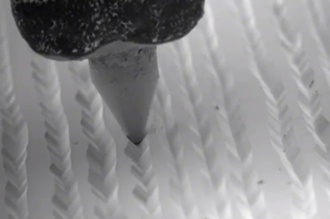
Close up view of needle slotting into the grooves. From Applied Science on YouTube.
Different frequencies require different grooves in the vinyl. To obtain more space for grooves on the vinyls, low frequencies are dampened while high frequencies are amplified. This was standardised in IEC 60098 and the same filtering appears on close to every vinyl in existence. Therefore you must apply the inverse filter before playing the vinyl, if you don’t want the music sounding like it’s played on a tin can.
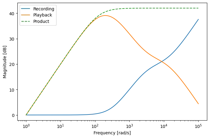
The filter characteristics of vinyl recording, playback and the final product between the two. Generating script available here.
You may notice that the resulting response is not flat, and this is by design, as this dampens the frequency components below the human hearing range of 20 Hz (~125 rad/s) that might have entered the system as a form of noise.
The pre-amplifier
The system is designed to have gain the 2 mV record player signal to 1 V and an input impedance of 47 kΩ and 220 pF in parallel and an output impedance of less than 1 kΩ.

Topology of the pre-amplifier circuit (in Danish).
The pre-amplifier consists of four blocks:
- The input impedance match, that satisfies the input impedance requirement. The impedance of the entire amplifier is exactly this block, as the opamp acts as a disconnect in parallel since the opamp has a very large resistance. In fact, the chosen opamp has a specified resistance of 10 TΩ.
- The gain control is responsible for partially lifting the amplification at the bandpass (the flat part of the product response) to match the requirement such that the 2 mV signal is amplified to 1 V. The resistor $R_{g2}$ is variable, as this resistor is partially hand tuned to account for component inaccuracies.
- The bandpass filter block implements the playback filter described earlier. It is constructed as two 1st order RC filters in series which are assumed uncoupled due to their high impedances.
- The last block implements the last part of the gain and the output impedance requirement. It is found that assigning more gain to the first opamp and less to the second reduces noise.
All the requirements are tested, including the total harmonic disturbance, which is the amount of harmonic components for each frequency within a given spectrum.
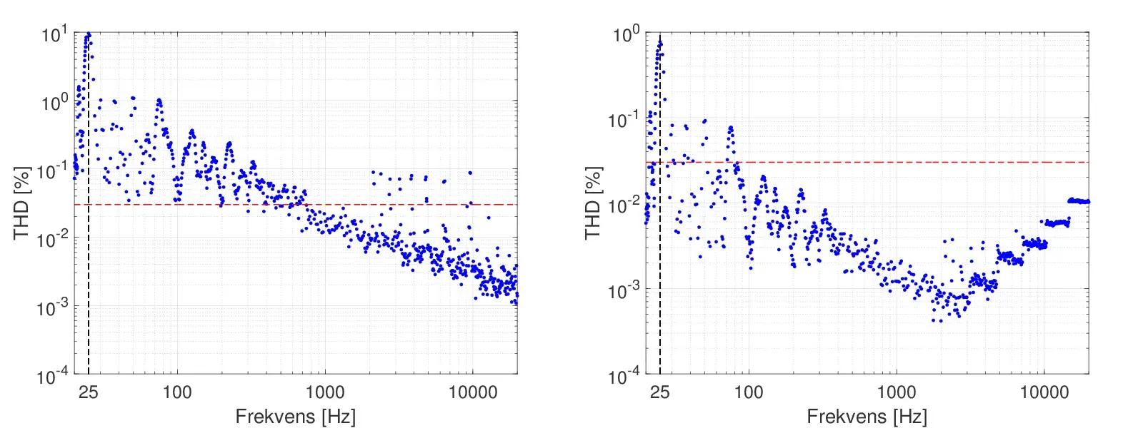
THD measurements from 20 - 10000 Hz for an input signal of 2 mV and 35 mV.
The requirement of gain, input impedance, output impedance and RIAA filters are upheld. The requirement of THD is not met at all and signal-to-noise ratio is just exactly not met.
The power amplifier
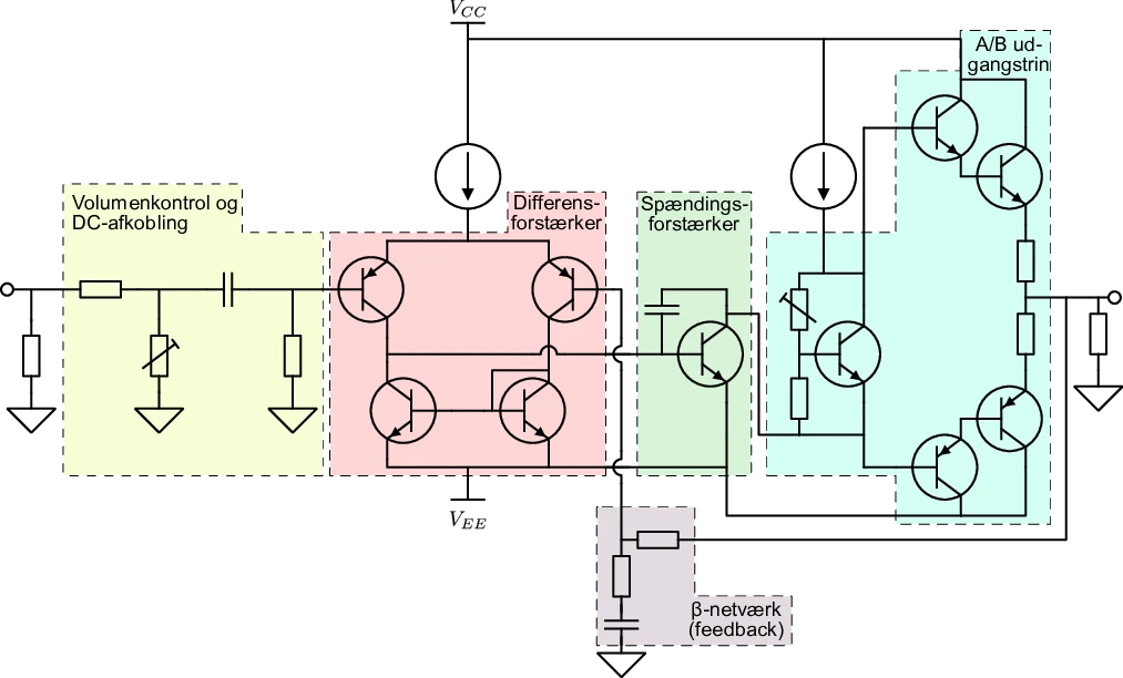
Topology of the power amplifier circuit (in Danish).
The supply voltage $V_{CC} = 25\text{ V}$ and oppositely $V_{EE} = -25\text{ V}$. The amplifier consists of 5 blocks, coloured for reference:
- A volume control is designed as a voltage divider with a variable resistor. A DC-decoupling is also done by way of an aggresive high-pass filter. This block also ensures the required input impedance of 10 kΩ.
- A differential amplifier, with the purpose of amplifying the difference between the input signal and the feedback signal. This block is quite complicated so I will not go into detail for the sake of readability. If you’re interested, check out this Wikipedia article.
- The current amplifier which is responsible for providing a large current to the output stage, as this leads to better noise characteristics as transistor diode non-linearity issues become less prevalent.
- The output stage is responsible for lifting the signal voltage one last time before sending it to the passive speaker. The stage is realised as a class A/B output stage, which means that the there is an amplifier for positive and negative signal phase and a bias voltage to pre-emptively excite the diodes above cut-off point. This has the advantage of less noise on the output at the cost of greater power consumption. The transistors are realised as Darlington pairs to further increase amplification.
- The $\beta$-network is a responsible for closing the loop and ensuring the required closed-loop gain.
The Darlington pairs can get quite hot due to the current they must endure, why a heat sink and fan is mounted (also seen on the picture). The printed circuit boards took a couple of iteration due to design mistakes, but turned out completely functional in the end.
The power amplifier had more requirements but managed to meet all of them except volume control which was unfulfilled due to an oversight during design.
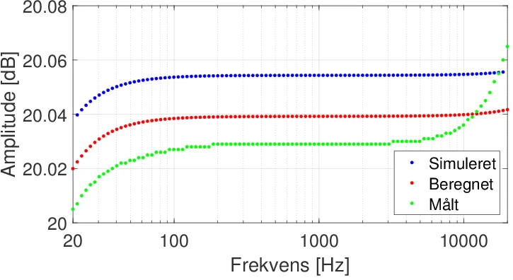
The output response of the filter as it was simulated by a circuit simulation tool, calculated numerically and measured.
All in all the amplifier design was deemed successful. Most requirements were met, especially those pertaining to the power amplifier, and it generally had low distortion why we were satisfied calling it a Hi-Fi (high-fidelity) amplifier. Some audio experts or hobbyists might scuff at such a statement, but I think we did well with the allotted time and our concurrent knowledge.
The music
On this semester, all the working groups were huddled in the back of an electronics laboratory. This space, separated by small room dividers (no taller than us) would act as the group room for approximately 30 people distributed amongst 6 groups. This led to no privacy but a large amount of banter between the groups. We where the only group making an amplifier for a record player specifically, but we managed to get ours working first. As such, the other groups were forced to listen to one of the only vinyls I owned: Nightfly to Venus by Boney M. Even though we later obtained other records, this record forever attained legendary status in our year.

Nighfly to Venus on a blackboard with a lyric from one of the lesser known songs.
Conclusion
This project remains one of the most memorable at the university. I think the reason is that it was all quite new. Another major reason is the comradery established by huddling all of us together like they did. The product wasn’t that technically challenging, but it was very rewarding. Some of these people I ended up working with all the way up until my Master’s Thesis!
Published 6. June 2023
Last modified 7. June 2023