From base 2 to base 10. BCD's and double dabble algorithm in VHDL
Most of the modern world counts in multiples of 10. This is probably because most of us have 10 fingers. When you see the number 6371 you are seeing
- 6 thousands
- 3 hundreds
- 7 tenths
- 1 ones
This is intuitive, but what most people don’t realize is that our way of counting implies that each digit is a power of 10: $$ 6731 = 6 \cdot 10^3 + 7 \cdot 10^2 + 3 \cdot 10^1 + 1 \cdot 10^0 $$
We say that our number system is in base 10 since we count 10 numbers (including 0) before switching to the next digit. In mathematics, this is typically denoted with the following notation
$$ (6731)_{10} $$
Computers operate in binary with each digit being a zero or one, meaning that they operate in base 2: $$ (6731)_{10} = (0001\ 1010\ 0100\ 1011)_2 $$
This corresponds to the number: $$ \begin{align} (0001\ 1010\ 0100\ 1011)_2 &= 1 \cdot 2^{12} + 1 \cdot 2^{11} + 1 \cdot 2^{9} + 1 \cdot 2^6 + 1 \cdot 2^3 + 1 \cdot 2^1 + 1 \cdot 2^0 \newline &= 4096 + 2048 + 512 + 64 + 8 + 2 + 1 \newline &= 6731 \end{align}
This is quite easy for us humans to compute, since our numbering system allows for base 10 operations. However, computers are limited to base 2 operations. This begs the question, how does a computer know how to display a number in base 10? How does a computer know that the binary number above should be displayed as a 6 followed by a 7, 3 and then a 1?
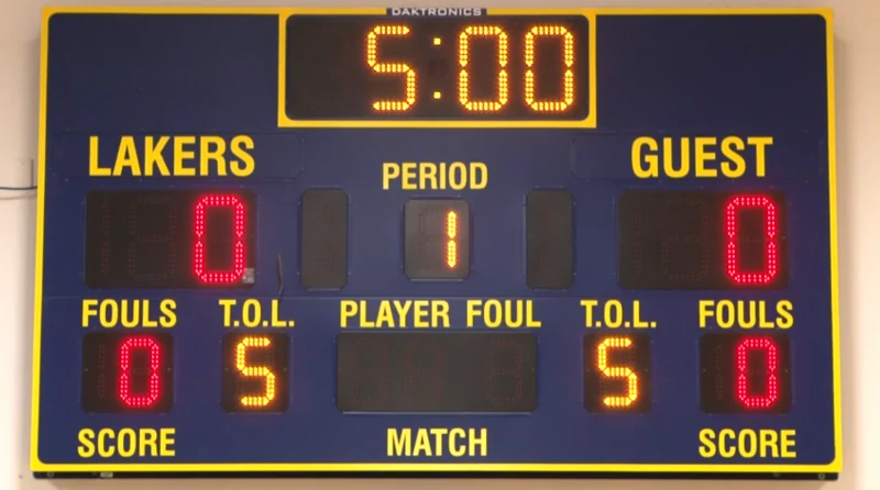
An LED scoreboard which uses 7-segment displays to show numbers also needs to internally calculate the base 10 decimals of a binary number.
It is much more effective for computers to compute in base 2, but sometimes they need to show us humans their results and most of us prefer that in base 10. So how does a computer convert a base 2 number to base 10? How does a computer know that the binary number above should be displayed as a 6 followed by a 7, 3 and then a 1?
It is convenient to represent the base 10 digits of a number in base 2 as a binary coded decimal (BCD). In a BCD each 4 bits represent a digit of the base 10 number. 4 bits can represent $2^4 = 16$ numbers and can thus represent any base 10 digit. An example of a BCD representation of the number 6731 is seen below:
Base 10: 6731
BCD: 0110 0111 0011 0001
       6    7    3    1
In a BCD we can simply look at each 4 bits to determine the base 10 decimal. Then we just tell the computer
- If the number is
0001, draw a segment - If the number is
0002, draw a 2 on the screen - …
- Continue until there are no more digits in the BCD
We could simply calculate the BCD of every binary number we would like to use and store them in a big table, accessing them when necessary. This is known as a lookup table and works well for scoreboards and the like, where the range of numbers is not too great (it is limited how many points can realistically be scored in a game of basketball for example). For other purposes, such as general computing, the range of numbers is practically infinite and a lookup table would require too much memory.
The double dabble algorithm
 Disclaimer
An algorithm for constructing a BCD from an arbitrary integer is known as the double dabble algorithm. This algorithm doesn’t use much more memory than the size of the input number but requires multiple operations and therefore introduces latency. The algorithm works as such:
Let the input number BI be a number, $n$ bits wide.
Let $d = \left\lceil n / 3\right\rceil$ be the maximum amount of digits in BI.
- Construct a number, denoted the scratch, as $4 \cdot d$ zeroes. Let $D_d, D_{d-1}, …, D_0$ represent the numbers in each 4 bits.
- Prepend the scratch with
BI. - For $x=0,1,…,d$, if $D_x \geq 5$, add 3 to $D_x$.
- Shift scratch left once.
- Continue from step 3 until
BIis zero.
A good example is found on Wikipedia which is modified to match the notation above:
 D2   D1   D0       BI
0000 0000 0000   11110011   Initialization
0000 0000 0001   11100110   Shift
0000 0000 0011   11001100   Shift
0000 0000 0111   10011000   Shift
0000 0000 1010   10011000   Add 3 to D0, since it was 7
0000 0001 0101   00110000   Shift
0000 0001 1000   00110000   Add 3 to D1, since it was 5
0000 0011 0000   01100000   Shift
0000 0110 0000   11000000   Shift
0000 1001 0000   11000000   Add 3 to D1, since it was 6
0001 0010 0001   10000000   Shift
0010 0100 0011   00000000   Shift
   2    4    3
       BCD
Why this works is not directly intuitive, but I will try to explain: When we see a $(5)_{10} = (0101)_2$ in any digit spot we know that the number will go beyond one base 10 digit in length during next shift whether or not the next bit is zero or one. This is because $(1011)_2 = 11$ and $(1010)_2 = 10$.
As such we must make this decimal roll over into the next 4 bits. Since each 4 bits represent $2^4=16$ numbers, we must add to the digit such that it becomes 16. We add 3 since the number is doubled upon shifting, as a shift in base 2 is a multiplication by 2, resulting in the number which would have been $(10)_{10}$ becoming $(16)_{10}$ instead which is $(0001\ 0000)_2$ in binary. Likewise, if the number was to be $(11)_{10}$ before, it becomes $(17)_{10}$ which is $(0001\ 0001)_2$ in binary. This continues to all the other digits and is the working principle of the double dabble algorithm.
VHDL implementation
VHDL is a specialized programming language for describing the structure and behavior of a digital electronic logic circuit. I used it extensively when building my own CPU during one of my university projects. This description can be used to simulate the circuit or employ it on an FPGA which is a bunch of digital logic components which can be connected at will.
Back in 2020 I constructed a double dabble algorithm in VHDL and uploaded it to GitHub. I made a clocked version that calculates the BCD of a 16 bit input number across several iterations and one which did it in one. The latter requires a very large amount of components aboard the FPGA and is therefore very inefficient, so I will be covering the clocked version.
The important code is found in ClockedDoubleDabbler16Bit.vhd and I will be presenting it here. First we initialize the component and add the used libraries:
|
|
The double dabble algorithm is a component which has a clock signal, a reset signal, an input and a BCD output.
The clock and reset signals are just a single bit each, while BIN and BCD are 16 bits and 20 bits respectively.
|
|
Firstly, the signals of the component are defined. These are scratch and cntr which keeps track of how many shifts have occurred. Both are initialized to all zeros.
Next, on line 7, a process is defined which runs on every clock cycle.
This process first checks the reset signal and resets if it is high.
Otherwise, the process performs the double dabble algorithm and adds 3 to the right spots if needed.
In line 31, the scratch register is shifted left once.
You may argue that this way of programming is terrible, and you are correct. The check of each base 10 decimal is hard coded and in reality you would have to look at each decimal sequentially, but this introduces a more complex program as well as extra latency. Furthermore, this double dabble algorithm was never used for anything in particular so runtime and memory usage were never a concern.
Published 16. June 2023
Last modified 3. December 2025